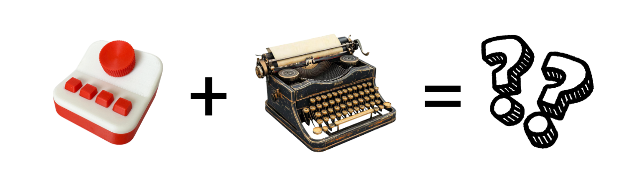
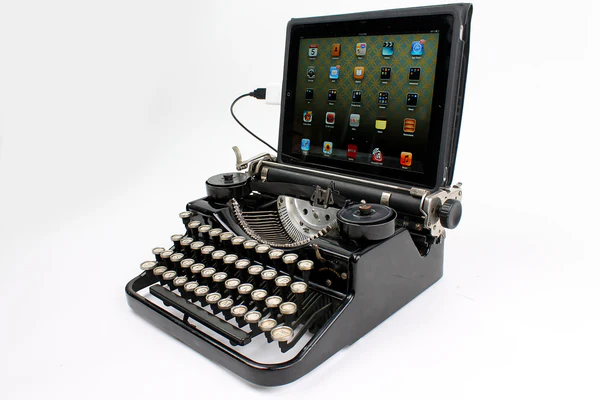
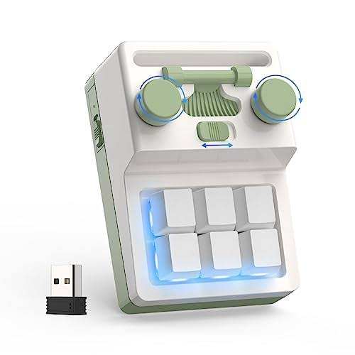
Inspo
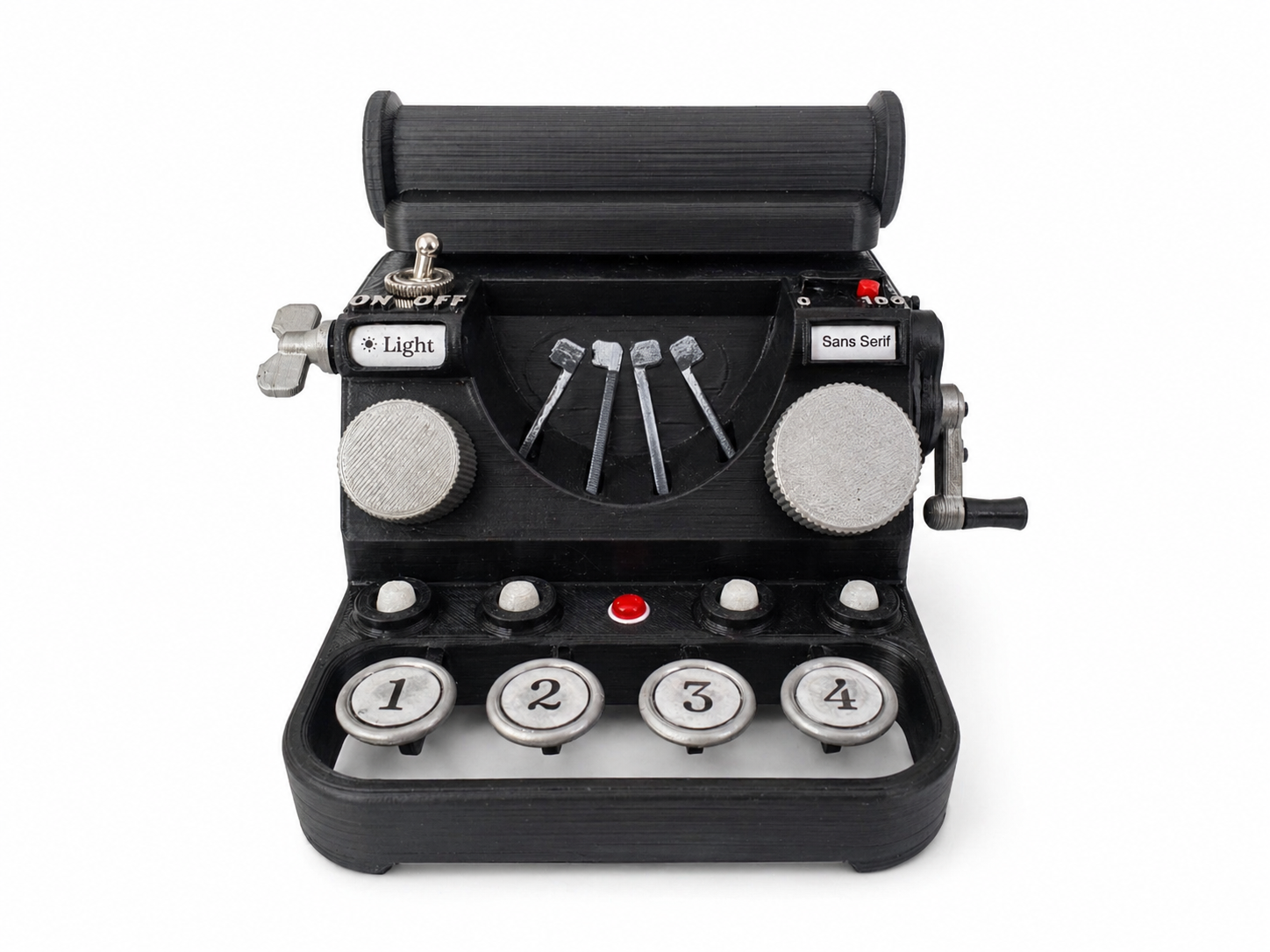
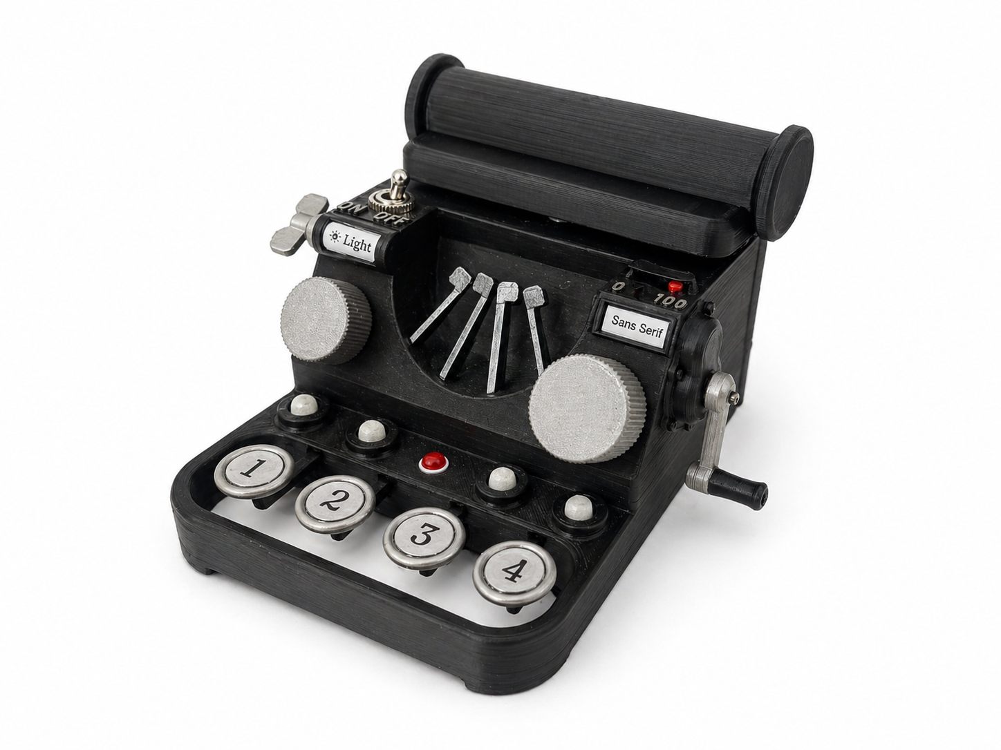
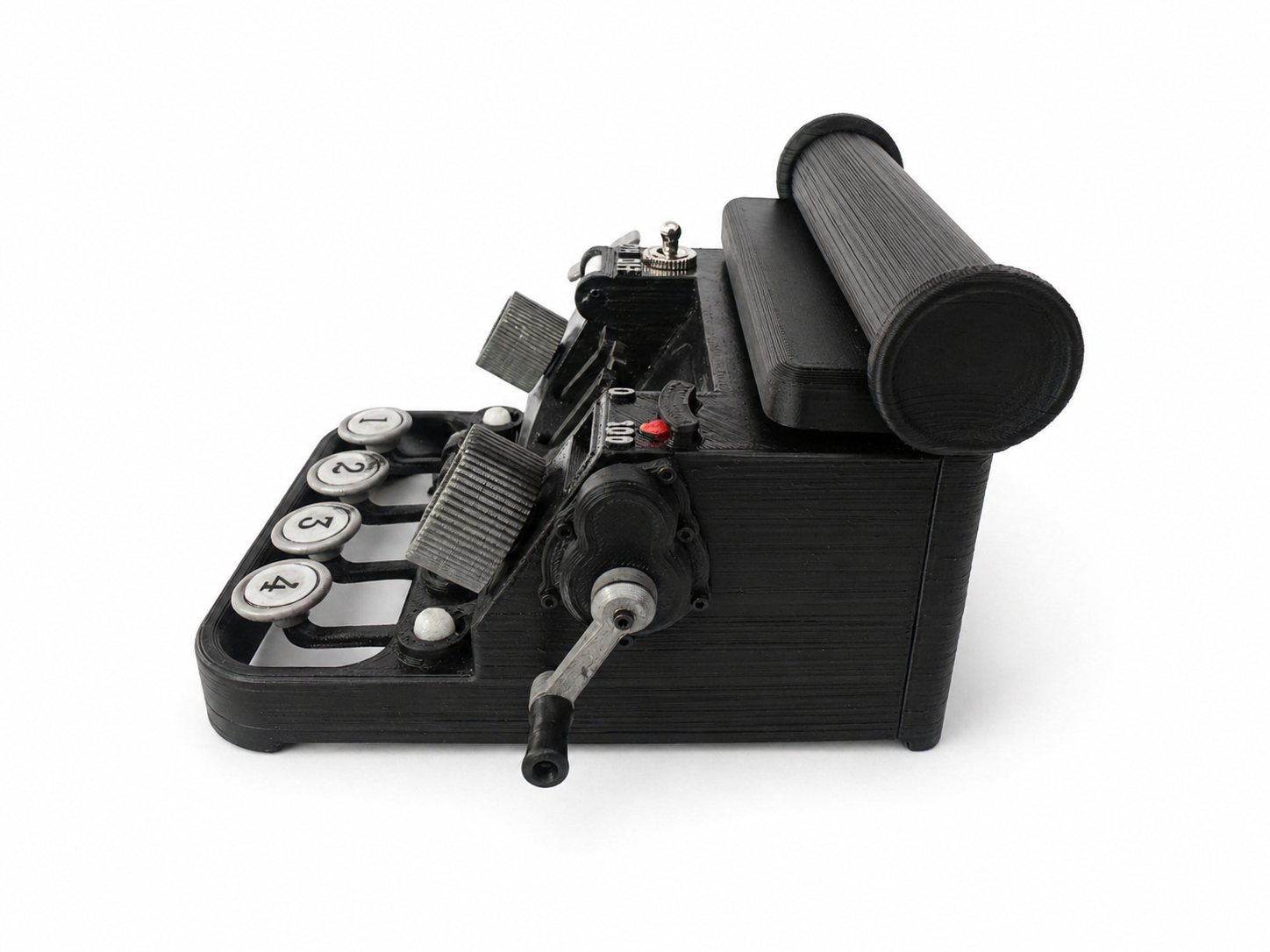
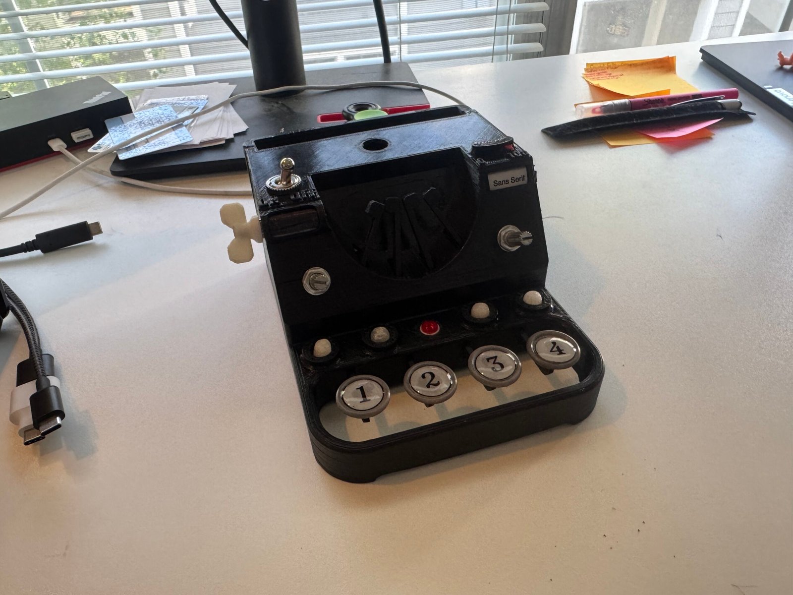
Final Product
Items Used
- ESP32-S3 N8R16 Dev Board
- Neodymium Magnets (16)
- Linear Hall Effect Sensors (9)
- DC Motor & H-bridge
- 9g Servo
- 18650 Lithium Battery
- 4 LEDs (formerly filament bulbs)
- MOSFETs
The Process
- Decided to keep same functional idea as IDC 1 but make the design more interesting
- Still webpage, still 4 buttons, still knobs to turn
- Inspired by old underwood typewriters, wanted to make this version tactile and fun to use
- Decided to include reset button, knob for font size, a carriage that moved, and the ability to “jam” the typewriter
- Later on included the on/off switch and battery voltage meter
- First step was to decide on all features and decide what parts to use for those features (encoders, motors, hall sensors, magnets, bearings, etc). Some of these decisions (and corresponding dimensions) were driven by items I already had in my box of junk (motor, bearings, magnets)
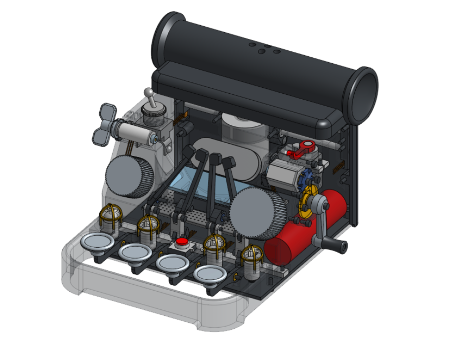
- Then I ordered all the stuff and once it came mocked it up in CAD
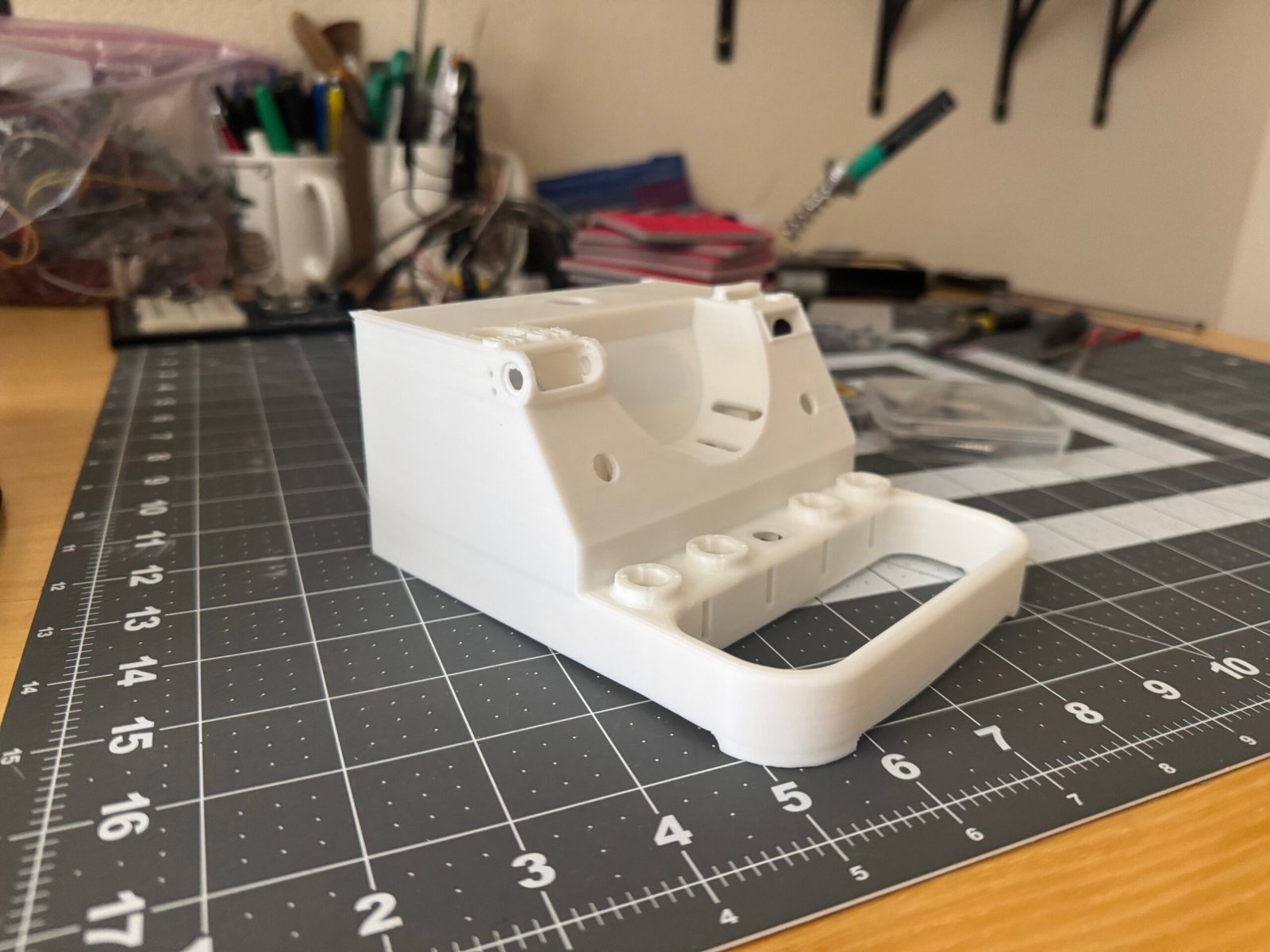
- Once I had the true size of all parts, I made a rough box shape of the typewriter by copying an underwood model, and began to work on linkage
- The goal for the linkage was to have a satisfying “thwack”, just like real typewriters, and for it to be smooth and never miss. I also wanted it to be as compact as possible to save space for all the other parts inside
- After the linkage was test printed and done, I designed the light mode and filter systems. I decided to use magnets and hall effect sensors because they were the smallest and most flexible option (encoders are way too big, and flat rotary encoders are expensive). Also, magnets offer absolute position reporting which is nice for the theme and filter subsystems because if you mess with them while the typewriter is off it doesn’t ruin the indexing.
- Decided to go with Geneva mechanism for the filtering, for no reason other than they’re cool and I had space on the side to mount it. Simple turning knob for the theme side.
- The motor, servo, linear rails, esp, and battery were put wherever they could fit afterwards
What worked
The core functions worked: you turned both encoders, the carriage moved as you turned them, the fonts changed, you saved them by pressing the keys, the LEDs turned on, you could reset them with the reset button. The light mode key made it dark or light mode
What didn't work
- It was meant to run a webserver off the ESP, and run off the battery. Unfortunately a few days before it was due when I was wiring it all together, I realized my hall effect sensors were for 5v and not 3, and I didn’t have a source of 5v. So I ordered the 3v ones (paid for overnight shipping too), but they didn’t come until after class on Thursday (first time amazon prime has ever let me down ironically). So I had to resort to plugging it into usb to give it 5v. And since it was already plugged in, I reused my serial code bits to communicate over usb.
- The filter system physically worked great (geneva drive was flawless), but the sensors couldn’t reliably read the 6 different states. The idea was to have two linear hall sensors mounted 90 degrees opposed, reading a bipolar magnet that rotated in the center of them (it was contained inside the actual filter drum). As it rotated, the sensors would read their respective values, and I’d make a lookup table. This all worked, but either the sensors were too far or magnet too weak, because the values were all near each other (They could read to 3000+, and all the values in the lookup table were within 100 of each other). This made it fairly unreliable. Sometimes when you turned it, it would work flawlessly, other times it would read the same value through all six rotations. Unfortunately there is no other solution besides hall effect sensors that provides endless rotation and absolute position sensing at all times, so this would’ve been a tough issue to fix, even with more time.
- The filament bulbs were not included on the final version, unfortunately. They fit perfectly, I had made copper wire cages for them, they looked great. Unfortunately I couldn’t get the MOSFETs to play nicely with them, and they would occasionally not power the bulbs. I learned (a little too late) that this was due to me not putting pull up and pull down resistors across the gates and sources, which in my breadboarding earlier were not needed. My PCB was too crowded to add them in after the fact, so I decided last minute (like, 5am Thursday) to swap them for LEDs which I could drive easily. I regret this, since the bulbs looked so good, but it is what it is.
- The electromagnet was a great idea, that I messed up on. It was a hand wound “hybrid” electromagnet that would sit right on the face where the keys striked, and catch them when you tried to save comic sans (thereby “jamming” the typewriter), to be released when the reset button was pressed. I had it all wired and installed, but unfortunately it was too weak to reliably catch the arms. It was a hybrid electromagnet with a neodymium core that would “almost” catch the arms, and the electromagnet part would just need enough power to push them over that threshold. But it wasn’t strong enough. It worked when I put weaker rubber bands on the returns of the keys, but then they felt mushy, so I decided to just not include the electromagnet. I couldn’t have just made it thicker with more wire because the motor was in the way (so I designed myself into a corner with that one)
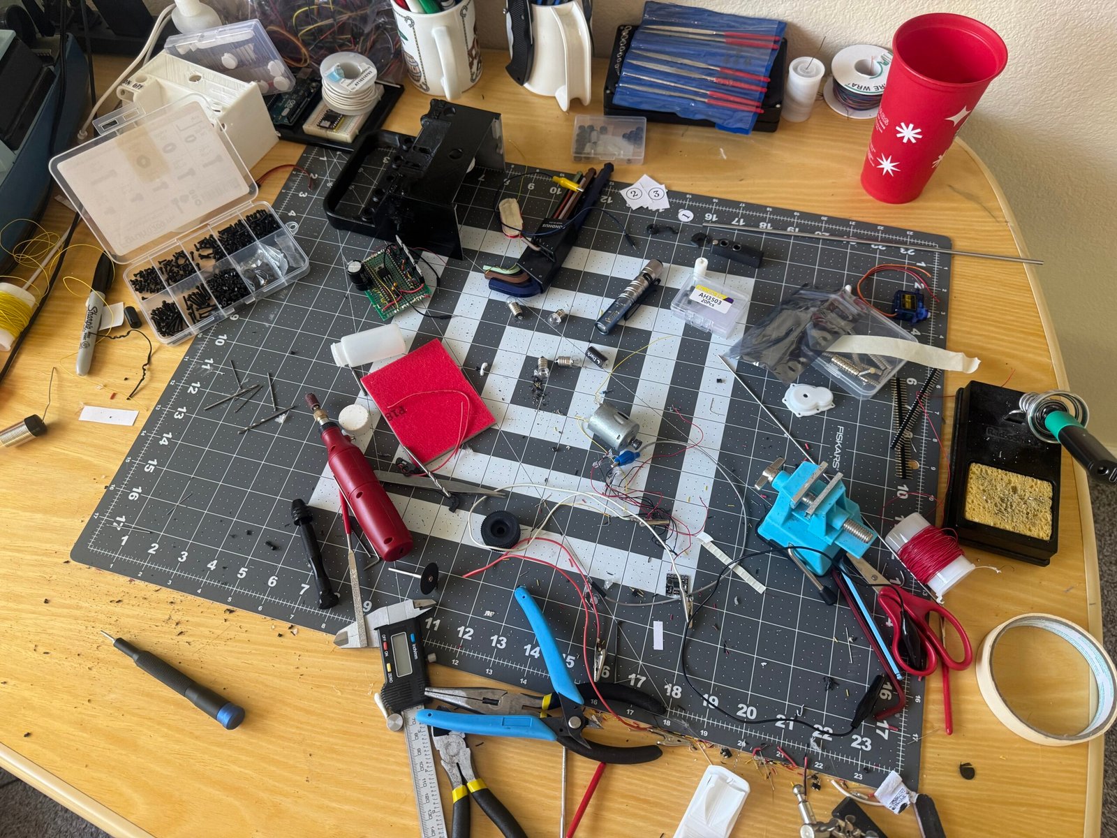
Process Photos

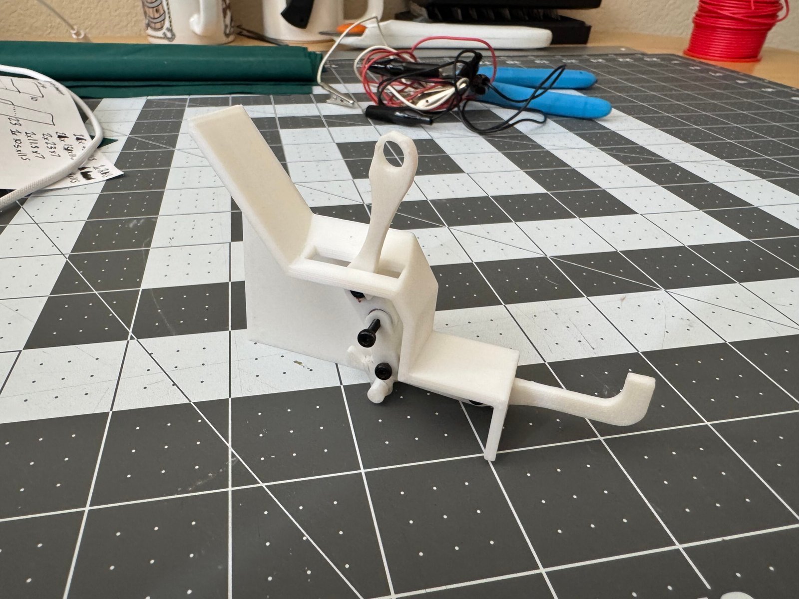
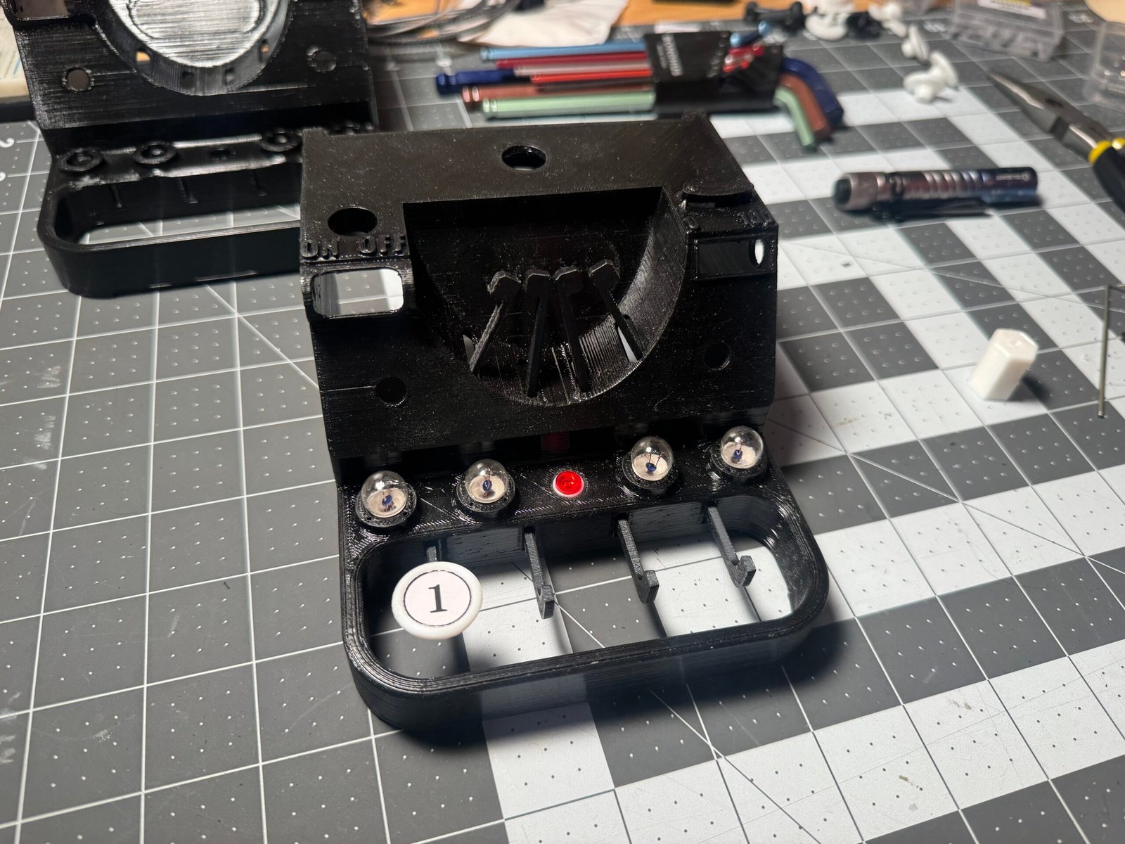
1st test print of linkage/key section. didn’t work 🙁
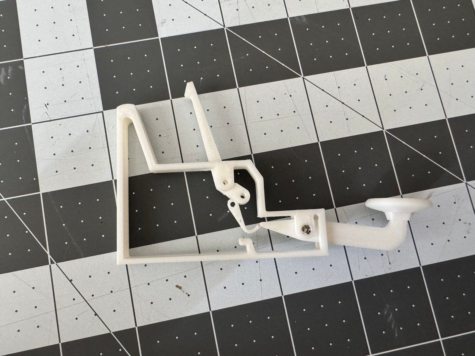
broken
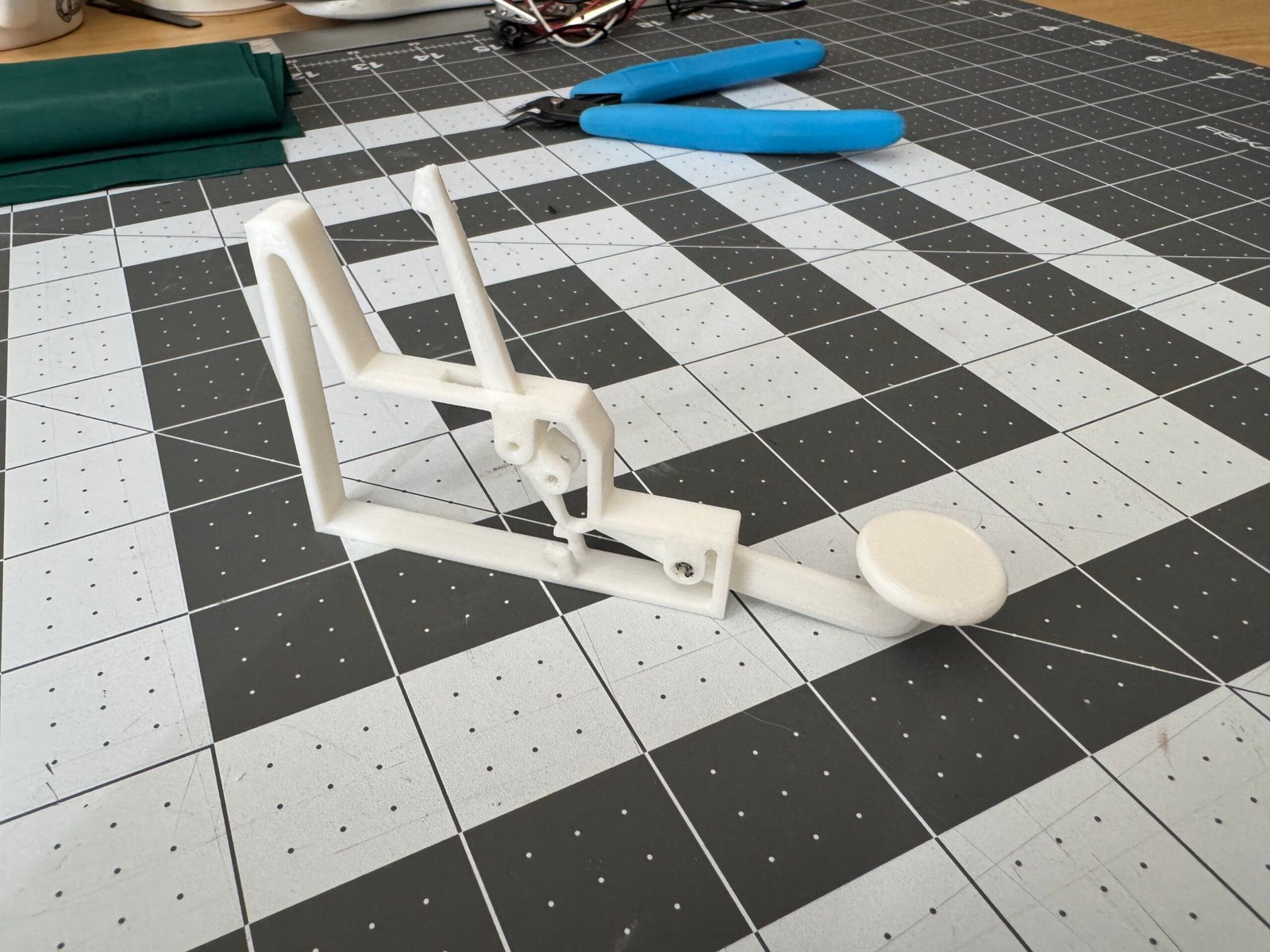
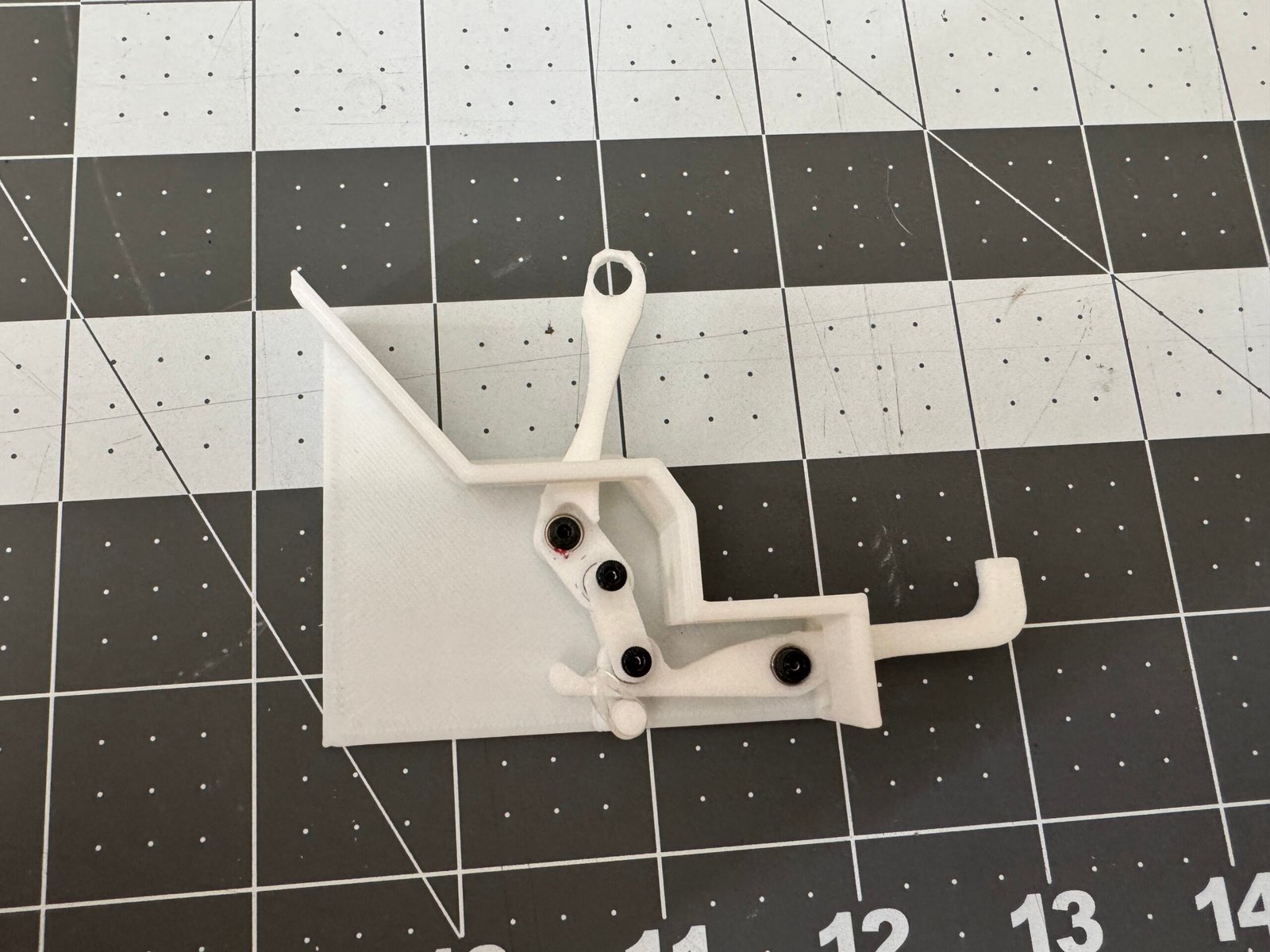
2nd test print
2nd test print
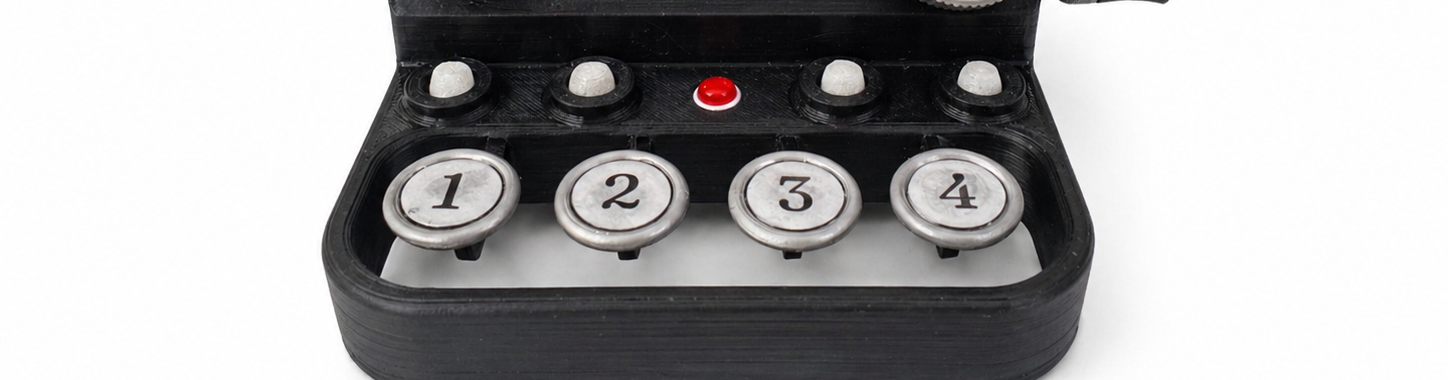
in action
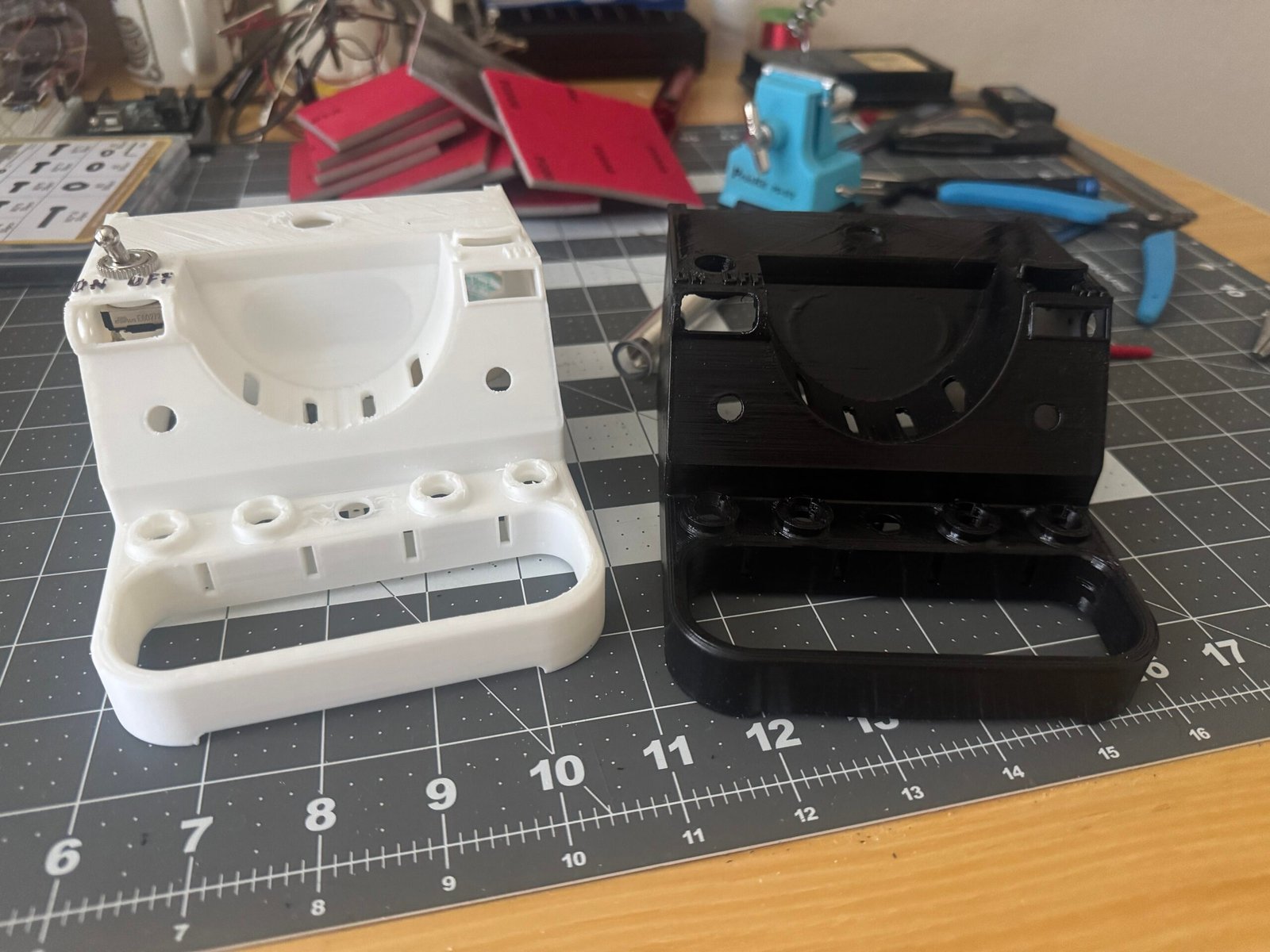
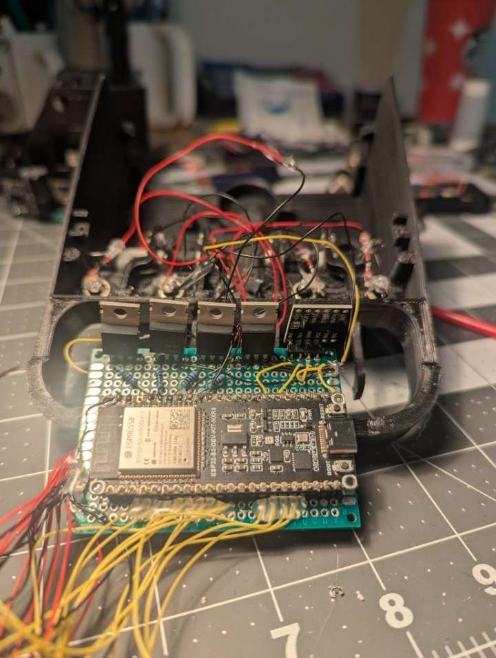
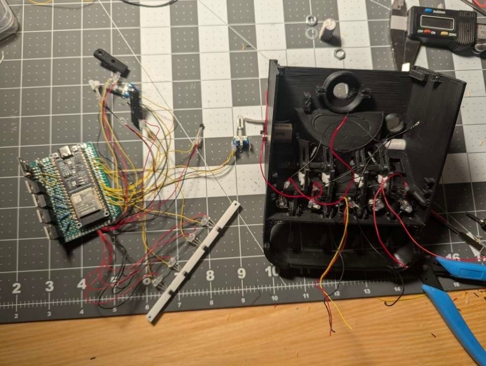
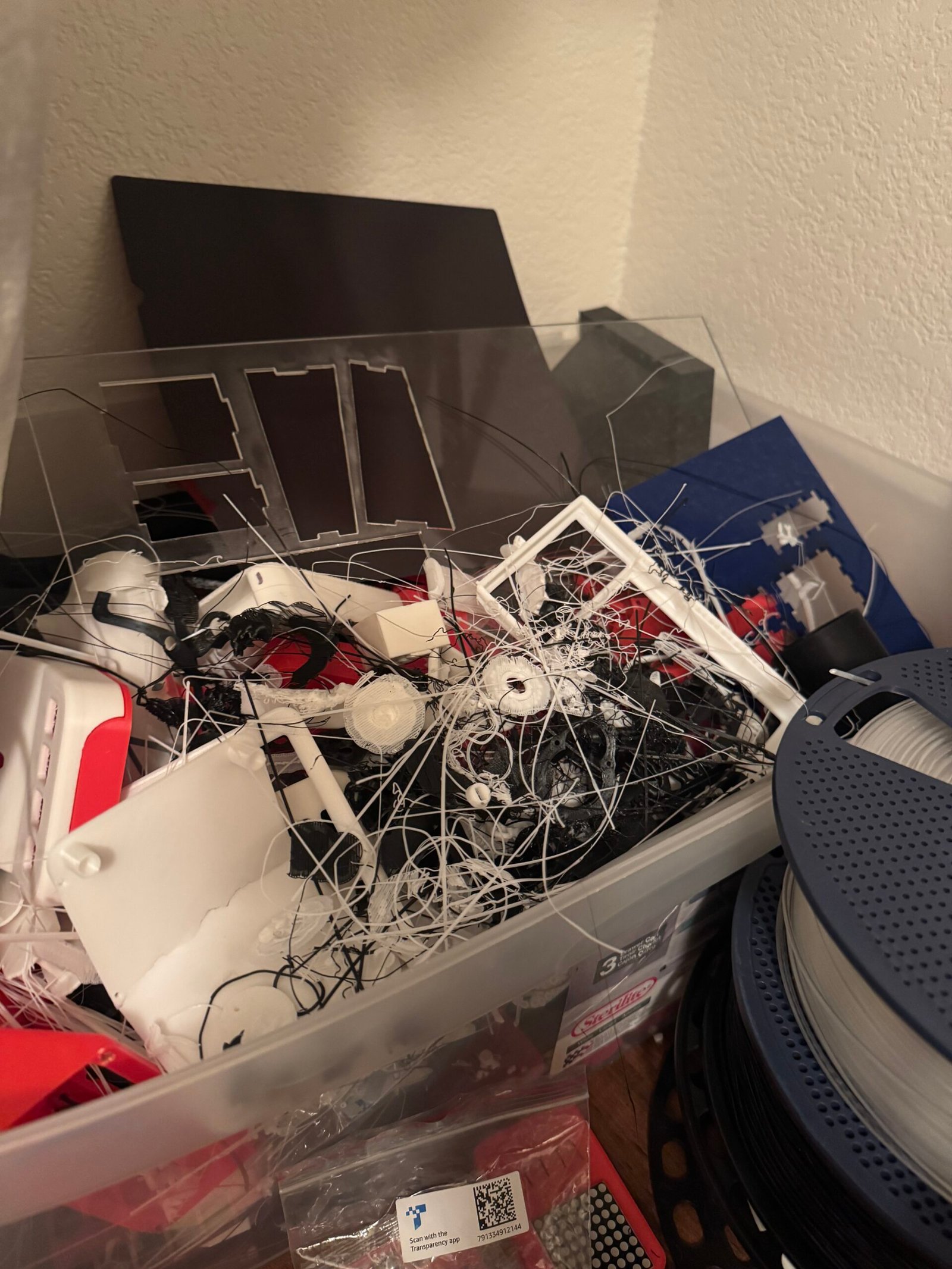
The aftermath